You know the problem: Your Bambu Lab printer just shifted a layer, the nozzle is scraping across the print bed, or the Z-axis suddenly loses its position. The print is ruined, and you're wondering if it's the usual suspects again — loose belts, worn-out rails, or just bad calibration. But sometimes the issue runs deeper: the encoder systems in your printer can no longer measure the actual positions of the axes accurately.
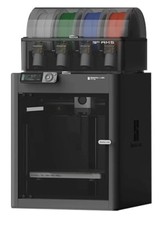
That's where the Bambu Lab Vision Encoder comes into play. This upgrade part is designed to improve your printer's position tracking. Instead of blindly relying on mechanical encoders, the system uses optical measurement for higher accuracy. It might sound like marketing jargon, but the physics behind it is solid: optical systems can capture movements with a resolution that mechanical systems simply can't achieve.
The Problem in a Nutshell
Most 3D printers rely on encoders that measure the rotation of the motors mechanically or magnetically. This works in principle, but these systems have their limitations. Mechanical encoders can become inaccurate due to wear, while magnetic systems suffer from temperature fluctuations and electromagnetic interference. Both types only measure the motor position — not the actual position of the axis.
This means: If a belt skips, a rail jams, or thermally expands, the printer knows nothing about it. It thinks the nozzle is at position X, but in reality, it's long gone elsewhere. You know the result: layer shifts, inaccurate dimensions, or complete print failure.
With fast printers like the Bambu Lab models, this problem becomes even more critical. When you're printing at 300 mm/s and making several direction changes per second, even the tiniest inaccuracies can quickly add up to visible errors. The high accelerations further amplify mechanical play.
The Cause Analysis
The Vision Encoder tackles the root of the problem: measurement. Instead of measuring the motor position and calculating the axis position from that, an optical system measures the actual movement of the axis. This works through a camera system that tracks high-resolution markings on a special tape or scale.
The key advantage lies in direct measurement. If the axis shifts by 0.02 mm due to thermal expansion, the optical system immediately captures this deviation. A mechanical encoder on the motor would never notice this shift because the motor hasn't moved.
The resolution of optical systems typically lies in the sub-micrometer range. This means positional changes of less than a thousandth of a millimeter are detected. For 3D printing conditions, this is more than sufficient — even at 0.1 mm layer height, you're working with hundreds of times this resolution.
Another point is immunity to electromagnetic interference. While magnetic encoders can be affected by motors, heating elements, or even a nearby smartphone, an optical system operates completely independently of such influences.
The Fix — Step by Step
The Vision Encoder is currently only compatible with the H2 Series. This limits its application significantly but also shows that Bambu Lab has specifically developed the system for their latest and most powerful printers.
Installation requires a complete replacement of the existing encoder system. You need to disassemble the axis, install the optical measurement system, and route the corresponding cables to the control board. This isn't a plug-and-play upgrade — you need technical understanding and should have disassembled a printer before.
After the hardware installation, the firmware configuration follows. The system needs to be calibrated so it can correctly interpret the optical markings. This calibration is critical: incorrect values lead to even worse results than the original system.
The software also needs to learn how to handle the new, high-resolution positional data. Too aggressive corrections can lead to vibrations, while too gentle corrections provide no advantage. This is where fine-tuning is required.
Prevention
If you're considering installing the Vision Encoder, you should first rule out all other causes of inaccuracies. An optical measurement system won't help if your rails are worn out or your belts are too loose. On the contrary: it will mercilessly show you how poor your mechanics really are.
First, check the belt tension. Too loose belts lead to backlash, while too tight belts unnecessarily strain the bearings. No encoder can compensate for either problem.
The rails must be clean and well-lubricated. Any stick-slip effect will be captured by the optical system and can lead to uneven movements. Use the right lubricant for your type of rail — linear rods need different maintenance than profile rails.
Thermal stability is another point. If your printer frame expands due to bed heating, even the most precise measurement won't help. Ensure constant ambient temperatures or use materials with a low coefficient of expansion.
When It's NOT This Problem
Not every positional error lies with the encoder system. If your prints are generally the right size but individual layers are misaligned, the problem usually lies elsewhere.
Mechanical play in the connections between the motor and axis can cause similar symptoms. Loose couplings, worn gears, or defective pulleys lead to sporadic positional errors that no encoder system can compensate for.
Vibration issues often manifest similarly to encoder inaccuracies. If the printer is on an unstable surface or the accelerations are set too high, positional errors arise from mechanical vibrations. A Vision Encoder would even measure these vibrations more accurately — but wouldn't solve the problem.
Software issues in the slicer can also lead to positional errors. Incorrect acceleration profiles, too high jerk values, or bugs in path planning create movement patterns that even the best hardware system can't execute cleanly.
Thermal problems are another candidate. If the hotend warps due to uneven cooling or the bed changes shape due to temperature fluctuations, apparent positional errors arise that have nothing to do with axis measurement.