Choosing the right infill pattern significantly affects the strength, print time, and material consumption of your parts. While many makers rely on standard settings, few know what actually happens within the layers. Gyroid, Honeycomb, and Lightning are three different approaches, each with its strengths when used correctly.
What These Patterns Physically Do
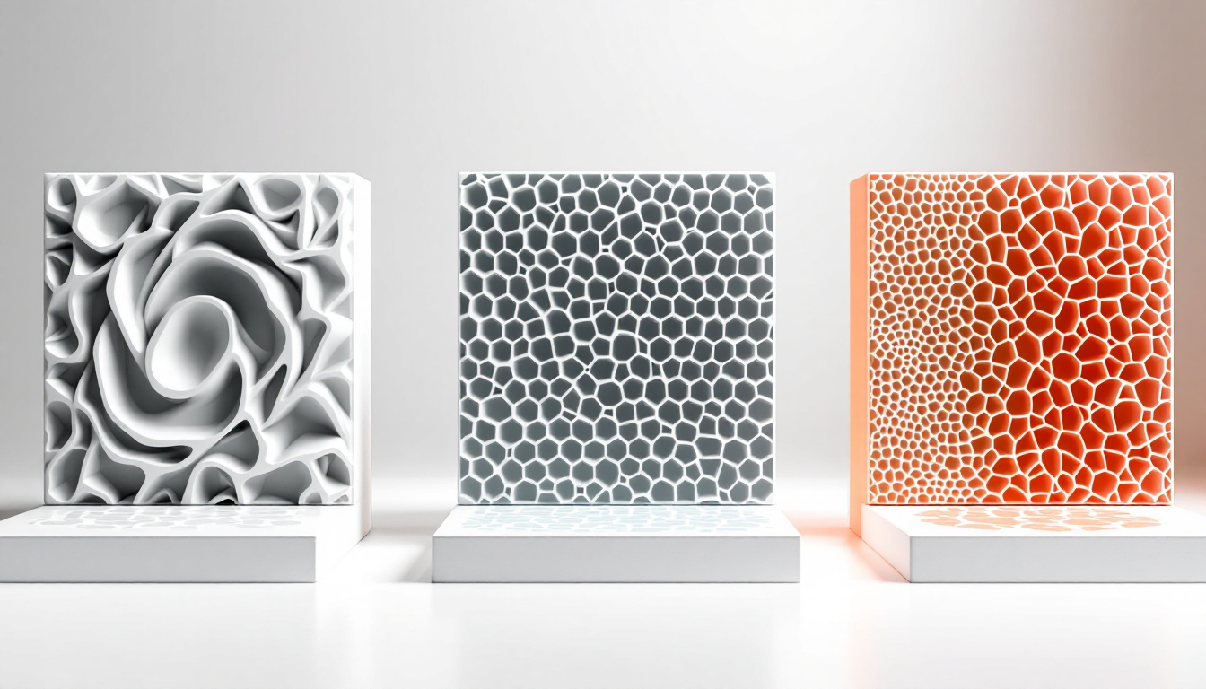
Gyroid is a mathematical structure that you can find in nature, like in butterfly wings. The curved paths create a three-dimensional lattice that is equally strong in all directions. The lines never intersect within a layer, which avoids material buildup. The spiral geometry connects the layers into an isotropic network.
Honeycomb mimics the hexagonal structure of honeycombs and creates optimal paths without intersections. The hexagonal cells distribute forces evenly and provide mechanical strength with minimal weight. However, any change in direction requires acceleration and deceleration of the print head, which extends the print time.
Lightning works differently: it grows from the outer walls to the top surfaces, becoming denser in the process. The branched structure exists only where it's needed — as support for the top layers. The rest remains almost hollow.
The Values That Work
For functional parts, you should aim for 20-40% infill density, while prototypes can get by with 8-15%. For highly stressed components, around 50% is sensible — going beyond that wastes material without a significant gain in strength.
Gyroid prints relatively quickly despite its complex geometry, as there are no intersections within the layers. You can run it at standard speeds, but you should watch for vibrations at high densities and speeds.
Honeycomb consumes about 25% more material than other patterns and can take up to twice as long. The mechanical properties justify this for structural parts that need to withstand real loads.
Lightning saves a lot of material — even more than adaptive cubic patterns, which already use a quarter less than standard infill. You get acceptable top layer support with minimal effort.
You should set the infill overlap between 8-12% with the outer walls. Less weakens the connection, while more creates visible lines on the surface.
When You Need to Deviate from the Standard
Translucent materials ruthlessly expose any infill errors. Here, Gyroid works best, as the uniform structure doesn’t allow unsightly patterns to show through. Honeycomb works too, but the straight lines can be distracting at certain angles of light.
Flexible filaments like TPU need patterns that can flex. Gyroid is king here, as the spiral structure allows deformations in all directions. Lightning fails completely — the rigid branches break when bent.
Large, thick-walled parts benefit from 30-50% infill to prevent sagging of the top layers. For thin walls under 2mm, you can often skip the infill entirely and instead increase the wall thickness to 3-4 perimeters.
Waterproof parts made from PETG work well with cubic infill at low density. The air pockets allow the part to float and provide thermal insulation.
If you want to fill parts with resin, Gyroid and Hilbert Curve are your only options. The large, contiguous cavities can be filled evenly, while Honeycomb creates thousands of small chambers.
The Most Common Mistakes
Rough tops occur when your infill doesn’t adequately support the top layers. Lightning at 10% density may look tempting, but it fails with less than 4-6 top layers. Increase the infill density to at least 20% or add more top layers.
Visible infill in translucent prints ruins the aesthetics. This usually happens due to too much overlap or unsuitable patterns. Grid and Triangle are problematic here — their intersections gather material and show through.
Weak layer adhesion occurs when the infill pattern doesn’t match the load direction. A part that is primarily loaded vertically needs different reinforcement than one subjected to lateral forces. Gyroid solves this with isotropic properties, but for extreme loads, you need to align the pattern accordingly.
Clogs in the nozzle with Grid and Triangle occur due to material buildup at the intersections. The print head moves over these bumps and can either pull filament or clog the nozzle. The characteristic clicking sound when passing over is a warning sign.
Advanced Tricks
Monotonic infill for top layers eliminates the ugly ridges that occur when left-to-right and right-to-left paths meet in the middle. The lines are consistently extruded from one side to the other, creating a uniform shine.
Adaptive infill density automatically adjusts the filling based on the distance to the nearest wall. Large cavities form in the middle, while the edge areas are filled more densely. This saves material without losing strength.
Infill anchors stabilize the start of each infill line and prevent under-extrusion at the beginning of the line. This is particularly noticeable in fast prints with many short infill segments.
The print order affects surface quality: infill before walls reduces the "vein" texture but can impact dimensional accuracy. Infill after walls is standard and prioritizes clean surfaces.
Variable layer heights for infill can save time on large parts. While the outer walls are printed at 0.2mm, the infill can run at 0.3mm — reducing the number of layers without visible effects.